


Deprecated: Function create_function() is deprecated in /www/wwwroot/puluo.top/wp-content/plugins/codecolorer/lib/geshi.php on line 4698
引言
上一篇我们完成了2D渲染器,接下来要实现3D几何体的绘制。其实3D比2D没有多太多内容,无非就是多了几步空间变换和一个视角控制的部分。首先,我们设置一下视角,为之后的三维渲染做准备。
空间变换与相机
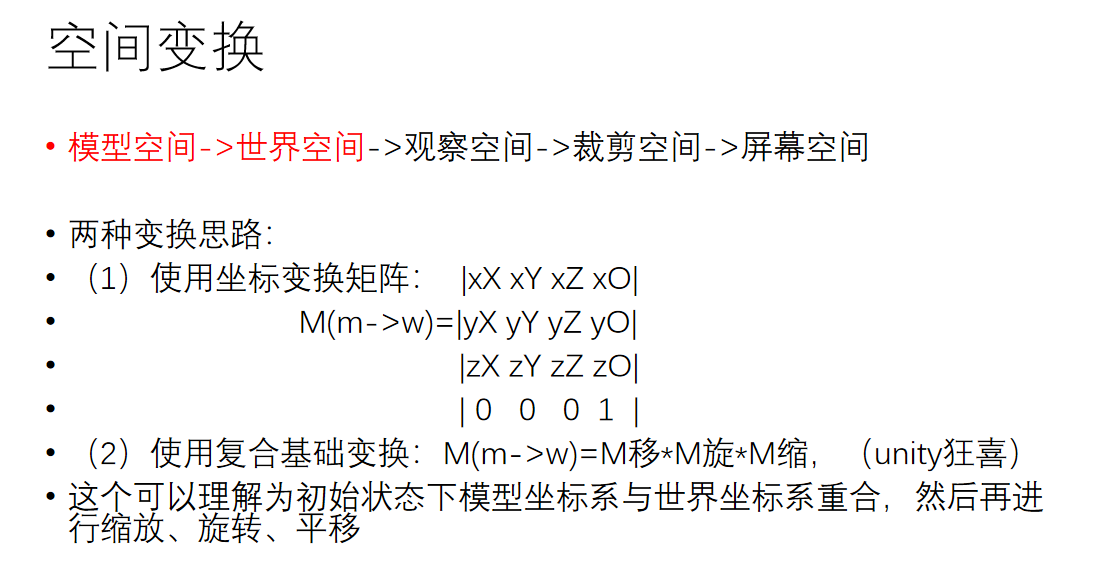
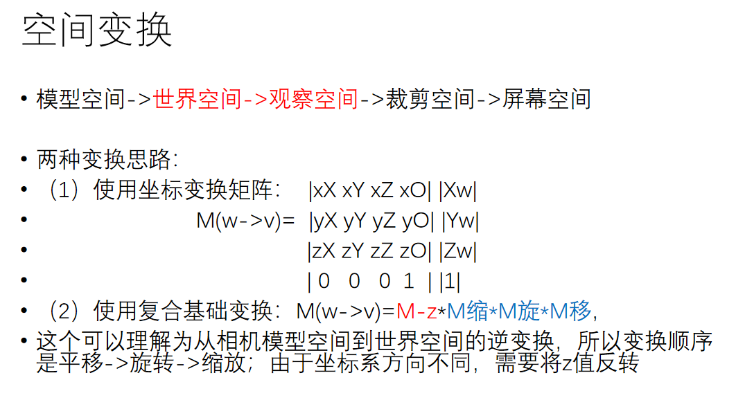
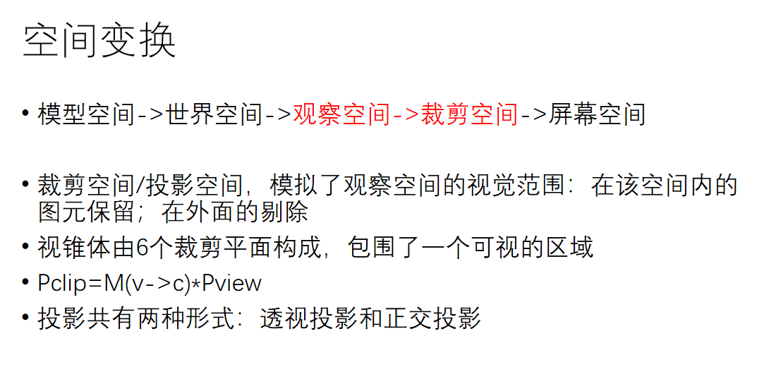
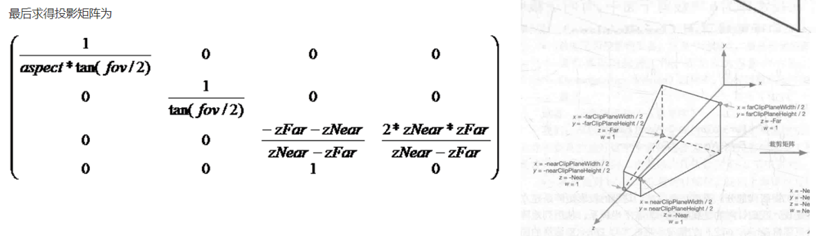
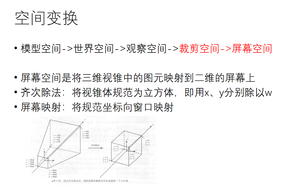
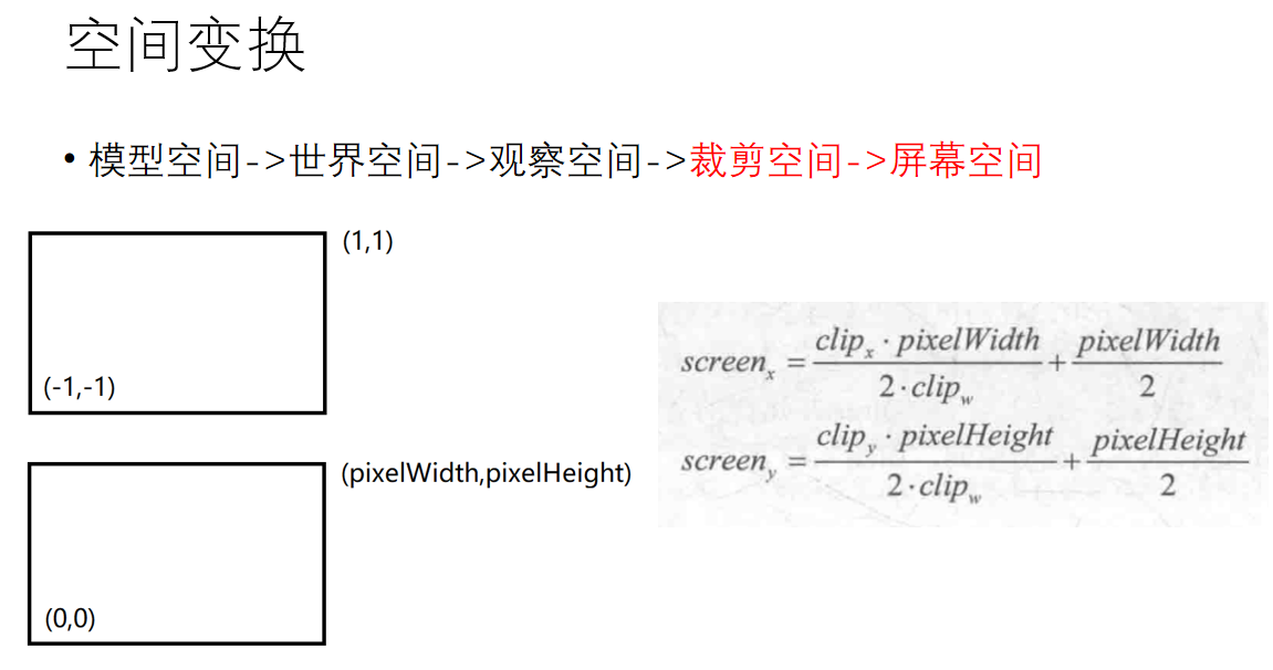
这里我们来简单谈谈空间变换。它的概念在unity渲染管线那篇文章中有详细介绍,大概就是要从模型空间变换到世界空间、变换到视角空间、变换到裁剪空间、变换到ndc空间、变换到屏幕坐标。因为这部分属于图形学入门的知识,再加上自己太懒不想打太多数学符号,因此直接上几张自己曾经做过的白板ppt:
好了,相信你对这几个空间变换有了一定的了解,那么接下来我们就补充一下Matrix类:
1 2 3 4 5 6 7 8 9 10 11 12 13 14 15 16 17 18 19 20 21 22 23 24 25 26 27 28 29 30 31 32 33 34 35 36 37 38 | void Matrix::lookat(Vector3D camPos,Vector3D tarPos,Vector3D up){ Vector3D xAxis,yAxis,zAxis; zAxis=-(tarPos-camPos); zAxis.normalize(); xAxis=up.product(zAxis); xAxis.normalize(); yAxis=zAxis.product(xAxis); yAxis.normalize(); normalize(); ele[0][0]=xAxis.x; ele[0][1]=xAxis.y; ele[0][2]=xAxis.z; ele[1][0]=yAxis.x; ele[1][1]=yAxis.y; ele[1][2]=yAxis.z; ele[2][0]=zAxis.x; ele[2][1]=zAxis.y; ele[2][2]=zAxis.z; ele[0][3]=-(xAxis.dot(camPos)); ele[1][3]=-(yAxis.dot(camPos)); ele[2][3]=-(zAxis.dot(camPos)); } void Matrix::perspective(float fovy, float aspect, float near, float far){ ele[0][0]=1/(aspect*tanf(fovy/2)); ele[1][1]=1/(tanf(fovy/2)); ele[2][2]=-((far+near)/(far-near)); ele[2][3]=-(2*far*near)/(far-near); ele[3][2]=-1; } void Matrix::viewPort(int left,int top,int width,int height){ normalize(); ele[0][0]=static_cast<float>(width)/2.0f; ele[1][1]=-static_cast<float>(height)/2.0f; ele[0][3]=static_cast<float>(left)+static_cast<float>(width)/2.0f; ele[1][3]=static_cast<float>(top)+static_cast<float>(height)/2.0f; } |
其中lookat矩阵是从世界空间转换到视角空间的矩阵,perspective矩阵是从视角空间转换到裁剪空间的矩阵,viewport是从ndc空间转换到屏幕坐标的矩阵,要注意的是中间其实还有一步从裁剪空间坐标转移到ndc空间的变换,方法很简单,只需要给x、y、z、w都除以w即可,因此我没有单写它的矩阵,但大家千万不要忘了这一步。
在三维世界中,相机是一个非常重要的物体,它决定了视口的视野。由于一般情况下游戏引擎中的相机以对象的形式呈现,因此我把这里的相机单独做成了一个类。
1 2 3 4 5 6 7 8 9 10 11 12 13 14 | #ifndef MAINCAMERA_H #define MAINCAMERA_H #include"vector3d.h" class maincamera { public: Vector3D pos,goal,up; float fov,asp,near,far; public: maincamera(); maincamera(Vector3D mpos,Vector3D mgoal,Vector3D mup,float mfov,float masp,float mnear,float mfar); void rotateY(float angle); }; |
首先相机作为一种对象(游戏物体),成员参数必须包括它在世界空间中的位置(pos)和旋转角度(这里使用的goal和up,分别表示相机看向的点以及相机自身的z轴方向,通过这两个向量可以唯一确定下来相机的旋转角度)。此外,在空间变换中我们知道:相机空间向裁剪空间变换时,其裁剪矩阵由相机的张角(fov)、asp(宽高比)、near(近裁剪面距离)、far(远裁剪面距离)来决定,因此这四个变量也必须要定义。
成员函数比较简单,构造函数种可以对相机的transform和属性参数进行设置,这里定义了一个rotateY函数,作用就是绕着Y轴旋转angle的角度,每帧调用rotateY就可以起到一种环绕浏览的效果。
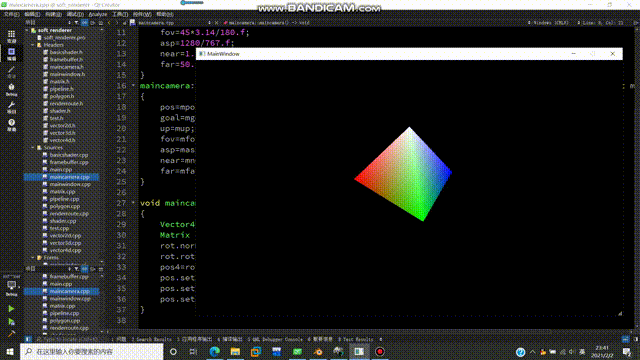
1 2 3 4 5 6 7 8 9 10 11 12 13 14 15 16 17 18 19 20 21 22 23 24 25 26 27 28 29 30 31 32 33 34 35 36 37 | #include "maincamera.h" #include "vector4d.h" #include "matrix.h" #include "stdio.h" maincamera::maincamera() { pos=Vector3D(0,4,-8); goal=Vector3D(0,0,0); up=Vector3D(0,1,0); fov=45*3.14/180.f; asp=1280/767.f; near=1.f; far=50.f; } maincamera::maincamera(Vector3D mpos, Vector3D mgoal, Vector3D mup, float mfov, float masp, float mnear, float mfar) { pos=mpos; goal=mgoal; up=mup; fov=mfov; asp=masp; near=mnear; far=mfar; } void maincamera::rotateY(float angle) { Vector4D pos4(pos.x,pos.y,pos.z,1); Matrix rot; rot.normalize(); rot.rotationY(angle); pos4=rot*pos4; pos.setX(pos4.x); pos.setY(pos4.y); pos.setZ(pos4.z); } |
现在我们得到了一个相机类。相机需要在执行渲染管线之前被创建出来,因此我们在renderroute类的loop中实例化一个相机类:maincamera *camera=new maincamera; 然后在渲染循环中把相机传入:pipeline->drawIndex(Pipeline::Fill,camera);
此时我们需要考虑的事情是:相机数据在管线中的什么位置会被用到。回顾渲染流水线的流程,我们可以知道,相机这个概念最早出现在顶点着色器中。在VS里,我们要将顶点从模型空间变换到裁剪空间,其中从世界空间变换到相机空间、从相机空间变换到裁剪空间这两大变换都需要相机数据。此时我们更改一下BasicShader类:
1 2 3 4 5 6 7 8 9 10 11 12 13 14 15 16 17 18 19 20 21 | #ifndef BASICSHADER_H #define BASICSHADER_H #include "shader.h" #include "polygon.h" #include "matrix.h" class BasicShader: public Shader { private: Matrix Mm2w; Matrix Mw2v; Matrix Mv2p; public: BasicShader(); ~BasicShader(){} virtual void setCam(Vector3D pos,Vector3D goal,Vector3D up,float fov,float asp,float near,float far); virtual V2F vertexShader(const Vertex &in); virtual Vector4D fragmentShader(const V2F &in); }; #endif // BASICSHADER_H |
其实就增加了三个变换矩阵:Mm2w是模型转世界,Mw2v是世界转相机,Mv2p是相机转裁剪。此外我们还增加了一个setCam函数,通过相机数据来设置上述的三大矩阵——通过pos,goal,up来构造Mw2v矩阵,通过fov,asp,near,far来构造Mv2p矩阵。因为是要构造矩阵,因此可以在matrix类里补充这两个构造矩阵的函数。
根据空间变换的内容,我们可以得到.cpp文件中setCam函数的具体写法:
1 2 3 4 5 6 7 8 9 10 11 12 13 14 15 16 17 18 19 20 21 22 23 | #include "basicshader.h" BasicShader::BasicShader() { Mm2w.normalize(); Mw2v.normalize(); Mv2p.normalize(); } void BasicShader::setCam(Vector3D pos,Vector3D goal,Vector3D up,float fov,float asp,float near,float far) { Mw2v.lookat(pos,goal,up); Mv2p.perspective(fov,asp,near,far); } V2F BasicShader::vertexShader(const Vertex &in){ V2F ret; ret.posM2W=Mm2w*in.position; ret.posV2P=Mw2v*ret.posM2W; ret.posV2P=Mv2p*ret.posV2P; ret.color=in.color; ret.normal=in.normal; ret.texcoord = in.texcoord; return ret; } |
在.cpp文件中我们来获取一下相机参数,这样可以构造出Mw2v和Mv2p两个矩阵了。拥有这些矩阵以后,我们便可以在顶点着色器中编写空间变换的代码了,如上述代码所示。之后我们来修改一下渲染管线中的内容:
1 2 3 4 5 6 7 8 9 10 11 12 13 14 15 16 17 18 19 20 21 22 23 24 25 26 27 | void Pipeline::drawIndex(RenderMode mode,maincamera *camera) { if(m_indices.empty())return; m_shader->setCam(camera->pos,camera->goal,camera->up,camera->fov,camera->asp,camera->near,camera->far); for(unsigned int i=0;i<m_indices.size() 3="">vertexShader(vv1),v2=m_shader->vertexShader(vv2),v3=m_shader->vertexShader(vv3); v1.posV2P/=v1.posV2P.w; v2.posV2P/=v2.posV2P.w; v3.posV2P/=v3.posV2P.w; v1.posV2P=viewPortMatrix*v1.posV2P; v2.posV2P=viewPortMatrix*v2.posV2P; v3.posV2P=viewPortMatrix*v3.posV2P; m_backBuffer->Cover(static_cast<int>(v1.posV2P.x),static_cast<int>(v1.posV2P.y),v1.color); m_backBuffer->Cover(static_cast<int>(v2.posV2P.x),static_cast<int>(v2.posV2P.y),v2.color); m_backBuffer->Cover(static_cast<int>(v3.posV2P.x),static_cast<int>(v3.posV2P.y),v3.color); if(mode==Wire) { bresenham(v1,v2); bresenham(v1,v3); bresenham(v2,v3); } else if(mode==Fill) { edgeWalkingFillRasterization(v1,v2,v3,1); //edgeWalkingFillRasterization(v1,v2,v3,2); } } } |
解析一下上面的代码,在进入管线之后我们要把相机参数给到对应的shader中,然后执行顶点着色器,完成空间变换。此时得到的V2F顶点位于裁剪空间当中,为了得到它们的屏幕坐标,首先要做一下齐次除法(直接除以w,即从裁剪空间变换到ndc空间),然后再乘一下从裁剪空间到屏幕空间中转化的矩阵viewPortMatrix。乘完之后,就得到了每个点的屏幕坐标。要注意的是,qt会对超出屏幕范围的点进行取模运算,这不是我们想要的结果,而且对于超出范围过多的点会导致爆栈,因此我们在光栅化的过程中,我们直接把屏幕之外的片元进行丢弃。
好了,我们的二维转三维的工作就完成了。接下来我们可以在renderRoute中自由定义一个mesh,装一下自己喜欢的几何体形状,然后在while循环中每帧调用相机绕y轴旋转的函数:
1 2 3 4 5 6 7 8 | while(!stopped) { pipeline->clearBuffer(Vector4D(0,0,0,1.0f)); pipeline->drawIndex(Pipeline::Fill,camera); pipeline->swapBuffer(); emit frameOut(pipeline->output()); camera->rotateY(0.01f); } |
现在距离转换还差最后一步:深度缓冲。因为我们只能看见离视角最近的内容,看不到远方的被遮挡的,因此我们可以在framebuffer中定义一个深度缓冲,在每次写入像素的时候都做一个如下的判断:if(current.posV2P.z<=m_backBuffer->depth[xx][yy])
(PS:深度其实可以用屏幕坐标下的z值来表示)
得到的效果如下:
纹理映射
讲道理,纹理映射本是一个很复杂的内容,但是因为前期的框架搭建比较良好+受cpu渲染性能影响没办法引入什么高端的纹理映射算法,因此这部分变得比较简洁。首先话不多说,先定义一个纹理类Texture:
1 2 3 4 5 6 7 8 9 10 11 12 13 14 15 16 17 18 19 | #ifndef TEXTURE_H #define TEXTURE_H #include"vector2d.h" #include"vector4d.h" #include<qmainwindow> #include <qstring> class Textures { private: int width,height,channel; QImage *pixelBuffer; public: Textures(); ~Textures(); void loadImage(const QString &path);17 Vector4D sample(const Vector2D &texcoord); }; #endif // TEXTURE_H |
这些成员大家应该都比较熟悉了。简单介绍下方法成员,loadImage是从你的磁盘中读入图片,sample就是根据传入的uv坐标,在纹理图上进行采样并返回采样结果。直接上.cpp文件:
1 2 3 4 5 6 7 8 9 10 11 12 13 14 15 16 17 18 19 20 21 22 23 24 25 26 27 28 29 30 31 32 33 34 35 36 37 38 39 40 41 42 43 44 45 46 47 48 49 50 51 52 53 54 55 56 57 58 59 60 61 62 63 64 | 1 #include "textures.h" 2 #include "QDebug" 3 4 Textures::Textures() 5 { 6 width=0; 7 height=0; 8 channel=0; 9 pixelBuffer=nullptr; 10 } 11 12 void Textures::loadImage(const QString &path) 13 { 14 pixelBuffer=new QImage(); 15 pixelBuffer->load(path); 16 width=pixelBuffer->width(); 17 height=pixelBuffer->height(); 18 channel=3; 19 } 20 21 Vector4D Textures::sample(const Vector2D &texcoord) 22 { 23 Vector4D result(0.0,0.0,0.0,1.0); 24 unsigned int x = 0, y = 0; 25 double factorU = 0, factorV = 0; 26 if(texcoord.x >= 0.0f && texcoord.x <= 1.0f && texcoord.y >= 0.0f && texcoord.y <= 1.0f) 27 { 28 double trueU = texcoord.x * (width - 1); 29 double trueV = texcoord.y * (height - 1); 30 x = static_cast<unsigned int="">(trueU); 31 y = static_cast<unsigned int="">(trueV); 32 factorU = trueU - x; 33 factorV = trueV - y; 34 } 35 else 36 { 37 float u = texcoord.x,v = texcoord.y; 38 if(texcoord.x > 1.0f) 39 u = texcoord.x - static_cast<int>(texcoord.x); 40 else if(texcoord.x < 0.0f) 41 u = 1.0f - (static_cast<int>(texcoord.x) - texcoord.x); 42 if(texcoord.y > 1.0f) 43 v = texcoord.y - static_cast<int>(texcoord.y); 44 else if(texcoord.y < 0.0f) 45 v = 1.0f - (static_cast<int>(texcoord.y) - texcoord.y); 46 47 double trueU = u * (width - 1); 48 double trueV = v * (height - 1); 49 x = static_cast<unsigned int="">(trueU); 50 y = static_cast<unsigned int="">(trueV); 51 factorU = trueU - x; 52 factorV = trueV - y; 53 } 54 Vector3D texels[4]; 55 56 pixelBuffer->pixelColor(x,y).red(); 57 texels[0].x = static_cast<float>(pixelBuffer->pixelColor(x,y).red()) * 1.0f/255; 58 texels[0].y = static_cast<float>(pixelBuffer->pixelColor(x,y).green()) * 1.0f/255; 59 texels[0].z = static_cast<float>(pixelBuffer->pixelColor(x,y).blue()) * 1.0f/255; 75 76 77 result = texels[0]; 78 79 return result; 80 } |
loadImage里读取图片的部分是Qt的固定写法,sample函数主要做了两部分:修正uv和采样。修正uv主要指的是如果uv坐标超出了范围,那么要自动进行循环拓展;采样部分比较简单,就是根据uv来对应到图片中的像素。这里本来写了双线性纹理采样,后来发现效果很不明显,而且很吃性能,所以就给去掉了。
那么如何让顶点知道自己用的是哪张纹理图呢?这里我们可以给顶点Vertex和V2F类都增加一个成员变量textureID,用来标识纹理,然后在Shader中把纹理存起来,在片元着色器中根据顶点的textureID编号来选择要采样的纹理:
1 2 3 4 5 6 7 8 9 10 11 12 13 14 15 16 17 18 19 20 21 22 23 | BasicShader::BasicShader() { Mm2w.normalize(); Mw2v.normalize(); Mv2p.normalize(); tex1->loadImage("D:/ice.jpg"); tex2->loadImage("D:/metal.jpg"); tex3->loadImage("D:/floor.jpg"); tex4->loadImage("D:/wall.jpg"); } Vector4D BasicShader::fragmentShader(const V2F &in){ Vector4D retColor; if(in.textureID==1) retColor = tex1->sample(in.texcoord); if(in.textureID==2) retColor = tex2->sample(in.texcoord); if(in.textureID==3) retColor = tex3->sample(in.texcoord); if(in.textureID==4) retColor = tex4->sample(in.texcoord); return retColor; } |
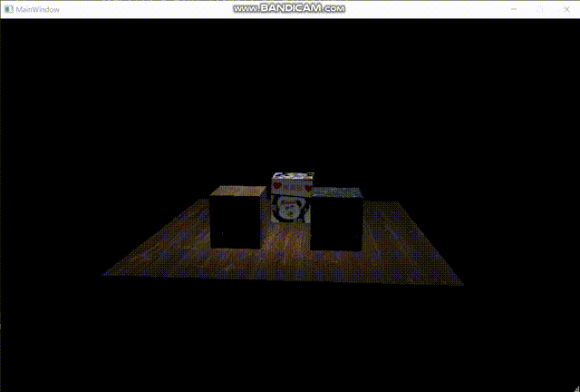
最后我们可以得到一个这样的效果:
怎么感觉正方体浮在表面上?仔细观察你会发现地板的纹理在来回扭动,使得正方体的变化和地板的纹理没有对应上,就会给人一种正方体浮在表面上的感觉。这个原因很简单,那就是在投影视角下,uv不再是线性的了。这个问题的解决方式很简单:在顶点着色器中,我们给texcoord除以一下w,这时候uv才会呈线性,此时我们再进行sample采样就能得到正确的结果。(在除以w之后,还要把w记录下来,然后在scanLinePerRow中别忘了再把w乘回来。如果你不在顶点着色器中记录w,渲染管线会在变换到ndc空间时把w置1,之后你再获取w就全是1了)
现在纹理正常了。
收尾——光照
最后我们来看一下光照模型。这里我们直接使用简易的兰伯特模型(因为性能实在罩不住了,太卡了)我们定义一个light类:
1 2 3 4 5 6 7 8 9 10 11 12 13 14 15 16 17 18 19 | #ifndef LIGHT_H #define LIGHT_H #include "vector4d.h" class Light { public: int kind; float intensity; Vector4D m_pos; Vector4D m_col; public: Light(){} Light(Vector4D pos,Vector4D col,int k,float i){kind=k;intensity=i;m_col=col;m_pos=pos;} Light(Light *l){kind=l->kind;intensity=l->intensity;m_col=l->m_col;m_pos=l->m_pos;} ~Light(){} }; #endif // LIGHT_H |
光照主要就是这几个属性:光照类型(已废弃)、光照强度、光源位置、光源颜色。方法只有个构造函数,.cpp文件直接空白。
接下来我们需要在renderRoute中把光源初始化出来,然后改写一下pipeline中drawIndex方法,把光源的指针传入到渲染管线,然后渲染管线再将光源传入到shader中,注意这步的传入并不是用的函数传参,而是我直接在shader中定义了一个光源成员变量,渲染管线只需要把这个成员变量修改一下即可。(这几步零零散散的改了好几处,而且每处都是一两句代码,所以我就不放具体修改的代码了)
接下来我们开始编写片元着色器,代码如下:
1 2 3 4 5 6 7 8 9 10 11 12 13 14 15 16 17 18 19 20 21 22 23 24 25 26 | Vector4D BasicShader::fragmentShader(const V2F &in){ Vector4D retColor; if(in.textureID==1) retColor = tex1->sample(in.texcoord); if(in.textureID==2) retColor = tex2->sample(in.texcoord); if(in.textureID==3) retColor = tex3->sample(in.texcoord); if(in.textureID==4) retColor = tex4->sample(in.texcoord); Vector4D n=Vector4D(in.normal.x,in.normal.y,in.normal.z,1); Vector4D l=lights->m_pos-in.posM2W; n.normalize(); l.normalize(); Vector4D last=Vector4D(lights->m_col.x*retColor.x,lights->m_col.y*retColor.y,lights->m_col.z*retColor.z,1); float tmp=n.dot(l); if(tmp<0)tmp=0; tmp=powf(tmp,0.8f); if(tmp>0.2f) retColor=last*tmp; else retColor=last*0.2f; tmp*=lights->intensity; retColor.w=1; return retColor; } |
首先我们获取到片元的法线,然后获取光源到片元的向量,接下来便可以使用兰伯特模型公式:Ild = k*I*(N·L),其中N表示顶点法向量,L表示从顶点指向光源位置的单位向量(主意指向,不要弄反了)。之后我们再乘一下光照强度,然后再根据效果调整一下强度曲线即可。
以下是最终效果图:
至此,软渲染器的制作完成。
Comments | NOTHING